
This article describes the implementation of a WiFi-connected PTZ camera system built around a Raspberry Pi Zero 2W. The Raspberry Pi hosts a web interface using Node.js and communicates with an Arduino Nano over USB serial using the Firmata protocol. A remote client browser captures input from its connected game controller and sends these control inputs over Wi-Fi to the camera system. Node.js receives and processes the inputs, then translates them into commands that are sent to the Arduino Nano. The Arduino, in turn, controls the stepper motors responsible for the camera’s pan, tilt and zoom/ focus movements.
Introduction
The author’s particular area of interest lies in assembling WiFi-connected devices, typically FPV systems incorporating a camera together with some form of device feedback and control. Such devices are generally operated remotely through a browser running on a distantly connected client machine. The device itself typically consists of a small Linux-based single-board computer, responsible for WiFi communication with the remote client, coupled to a microcontroller that performs the real-time hardware control tasks.
In previous projects, I have relied on the Apache web server, running on the SBC, to serve the web interface, with C code, PHP and JavaScript scripting providing the application logic. I have also used I²C communication to interface with a slave microcontroller, together with dedicated firmware to perform the real-time control functions. While this architecture is workable, it has proven less than ideal in practice. It introduces unnecessary complexity, divides the application logic between disparate software environments, and requires the development and maintenance of dedicated microcontroller firmware.
Although PHP running under Apache is sufficiently performant for the application, the memory footprint of the web server is a significant concern, particularly on a Linux SBC with only 0.5 GiB of RAM, of which 256 MB must be reserved for GPU-based image processing. There is also a more practical difficulty with the use of the optimized Arduino I²C Slave Peripheral routines developed for earlier projects. Although these routines perform well, their complexity makes them difficult for other users to understand or adapt. Consequently, despite their technical merits, they have come to be regarded as having relatively little practical value beyond the projects for which they were originally developed.
Accordingly, in developing this PTZ camera system, which serves as a pilot for a more sophisticated remotely operated telescope project, I decided to investigate Node.js as an alternative platform for both serving the web interface and implementing the application logic. Node.js offers a particularly attractive combination of execution speed and modest memory requirements. At the same time, I investigated the Firmata serial protocol, together with Node.js’ firmata.js library, as a replacement for I²C communication.
This approach eliminates the need to develop dedicated firmware for the microcontroller, since the logic governing real-time operation can instead be implemented in JavaScript on the SBC. The microcontroller effectively becomes a runtime-configured peripheral, with its behavior established through the Firmata USB serial connection between the Linux host and the 8-bit slave processor.
Firmata?
Firmata is, fundamentally, a communication protocol that provides an interface between a host system and a microcontroller running a suitable implementation of Firmata firmware. Rather than developing application-specific firmware for the slave microcontroller, the developer installs the appropriate Firmata firmware and then configures and controls the microcontroller at runtime. Hardware configuration and manipulation are performed by calling generic functions on the host system through a Firmata client library.
There is, however, no single, universally applicable implementation of Firmata. Multiple versions of the protocol exist, along with several Firmata firmware implementations, with support for a range of microcontrollers. There are also a variety of client libraries, each intended for use with a particular host programming language. Identifying a combination that worked reliably proved to be something of a challenge. The following is the configuration with which I ultimately had success:
- Firmata Protocol 2.5
- ConfigurableFirmata Server Arduino Library version 2.10.1
- Arduino Nano 5V 16MHz ATmega328p
- firmata.js Node.js JavaScript Client Library version 2.3.0
- Node.js JavaScript runtime Engine version 12.22.12
Firmata Server Setup
The initial setup is straightforward. Download ConfigurableFirmata Server Arduino Library version 2.10.1, then follow these installation instructions to install and compile the library for an Arduino Nano fitted with an ATmega328P. Although visually and electrically similar, a Nano fitted with an ATmega328PB is not compatible with ConfigurableFirmata.
As its name suggests, ConfigurableFirmata is designed to be configured according to the hardware functions required by the application. In this project, its optional accelStepper module is used to control the stepper motors. Consequently, the corresponding header include in the master sketch, ConfigurableFirmata.ino, must be uncommented and enabled. This file is located in the examples/ConfigurableFirmata sub-directory of the library.
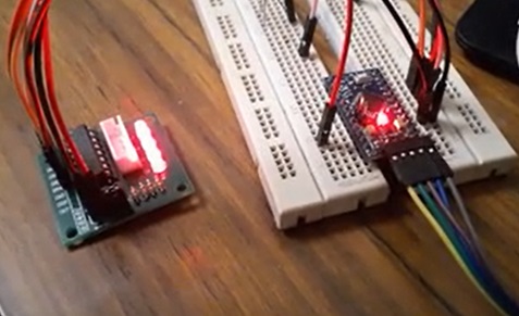
Early testing on an Arduino Pro Mini.
ConfigurableFirmata Issue
The introduction of the AccelStepper Arduino library was something of a watershed moment for hobbyist stepper-motor users. It provides both position and speed-based control, with smooth acceleration and deceleration and non-blocking operation. Its ease of use, reliability, support for multiple motors, and ability to perform other tasks while motors are moving have made it extremely popular.
Unfortunately, even the most recent ConfigurableFirmata interface to AccelStepper is incomplete. It supports position-based stepper control, but omits the library’s direct speed-control functionality. In particular, it uses the setMaxSpeed(speed)/run() pairing for position-oriented operations such as runToPosition(), while omitting the setSpeed(speed)/runSpeed() pairing intended for speed-based control.
For our PTZ control application, we need reliable access to both position and speed-based stepper control. To achieve joystick-based speed control, we have therefore had to work around ConfigurableFirmata’s limitations by using its position-control functionality in an unconventional way.
Firmata Client Javascript
The complete listing of the pathfinder project’s JavaScript code is linked below. Before examining it in detail, however, there are two aspects that warrant discussion: first, how the Firmata server is configured for stepper motor control, and second, how the project’s implementation makes unconventional use of its AccelStepper module.
The slave-control.js file contains a class built around the firmata.js client library, providing the interface through which the Firmata server is configured and controlled. The file begins by importing the Firmata module:
// slave-control.js
const Board = require("firmata");Further into the class, a configuration method establishes the type, pin assignment, and operating mode for each stepper motor connected to the slave micro-controller. For brevity, only the configuration for the first motor is shown below:
  configureSlave() {
    this.board.accelStepperConfig({
      deviceNum: Device.PAN,
      type: this.board.STEPPER.TYPE.FOUR_WIRE,
      motorPin1: 2,    // IN2 for 28byj-48-5v unipolar stepper motor drive board.
      motorPin2: 3,    // IN4                        ''
      motorPin3: 4,    // IN1                        ''
      motorPin4: 5,    // IN3                        ''
      stepSize: this.board.STEPPER.STEP_SIZE.WHOLE,
    });
    console.log("x device 0 configured");
    .
    .
    .
}Once initialisation of the server board is complete, including the configuration described above, the class provides a number of functions for controlling the individual stepper motors. Again, ConfigurableFirmata’s access to the underlying AccelStepper module, provides a rather different control model from that required by this application. It expects the host to specify a target position relative to the motor’s current position, together with a maximum speed at which that position should be reached. The module then determines the direction of travel, accelerates the motor towards the target, and subsequently decelerates it as the target is approached. This behavior is useful for positional control, but is not what we require for a responsive PTZ system.
Our PTZ application instead requires an interface through which the step rate and direction of each motor can be changed rapidly and repeatedly. To achieve this using ConfigurableFirmata’s AccelStepper calls, we effectively co-opt its position-only-oriented interface. We repeatedly supply it with a deliberately distant and otherwise irrelevant target position, using that target solely to establish the desired direction of travel, together with the speed at which the motor should run.
setStepperValue(deviceNum, value) {

    // Request the current position first (this is asynchronous)
    this.board.accelStepperReportPosition(deviceNum, (currentPosition) => {
      // Store the reported position
      this.posnValue[deviceNum] = currentPosition;
      .
      .
      .
        // Calculate new target position and speed
        const newPosition =
                 currentPosition + Math.round(value * this.positionIncrement);
        const newSpeed = Math.round((value - DEAD_BAND) * this.maxStepsPerSec);
        .
        .
        .
          // Set the speed (this command returns immediately)
          this.board.accelStepperSpeed(deviceNum, newSpeed);
          // Set arbitrary, large target to indicate direction
          this.board.accelStepperTo(deviceNum, newPosition);
        .
        .
        .
    });
}We therefore have direct control over the speed and direction of all three stepper motors, with each motor governed by the deflection of the corresponding joystick axis on the client’s game controller. This is a simplification of the actual implementation, but it should make the otherwise non-intuitive portion of the JavaScript code easier to understand.
The Node.js runtime executes an index.js application script, which instantiates the class described above and serves the index.html interface to the client browser. Once the page has loaded, JavaScript running in the browser communicates with the corresponding back-end JavaScript functions running on the Node.js server. Data is exchanged in both directions, with the client transmitting joystick inputs to control the PTZ system, and the server returning information describing the current state of the device.
Hardware & Wiring
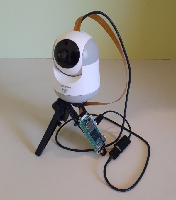
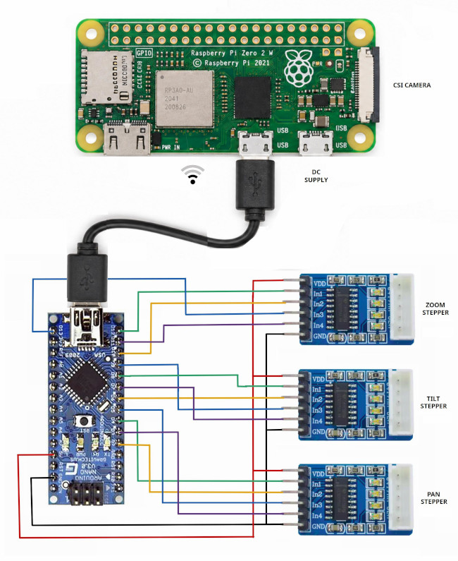
As this was primarily a path-finding exercise, the hardware implementation was deliberately modest. I simply gutted a $5 WiFi camera with its original, rather inadequate pan and tilt mechanism, retaining the small stepper motors, and replaced its original PCB with an inexpensive OV5647-based 5MP camera module. The Arduino Nano and stepper motor control circuitry are housed within the original enclosure, while the camera module and Nano are connected to a Raspberry Pi Zero 2W mounted externally.
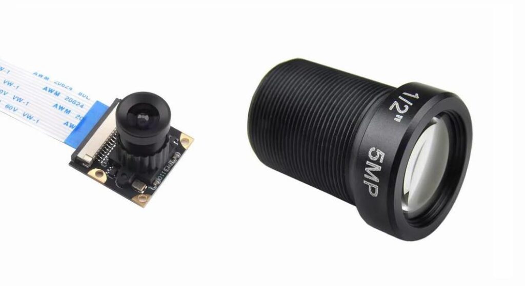
The camera lens used was an inexpensive 25 mm, 5MP telephoto lens with an M12 × 0.5 mounting thread. More capable lenses are readily available, although their prices tend to increase commensurately with their optical performance.
Only the pan and tilt functions were implemented in the interim prototype, although each axis was fully tested and is supported by the source code. The zoom/ focus function, though implemented in software, was not connected to the prototype hardware.
OS Setup
Because the the Node.js package Firmata.js used in the project is quite dated, and depends on several other similarly outdated Node.js packages which can be difficult to install and compile on more recent operating systems, I have chosen the relatively dated and minimal Buster release of the Raspbian OS. This provides the necessary compilation support for Firmata.js’ dependent modules, while also keeping the operating system’s memory footprint to a minimum.
The Firmata.js client library for Node.js, which supports the Firmata protocol version 2.5 used by this project, requires Node.js 12.22.x. We will therefore install the early 12.22.12 release of Node.js.
We will also install a version of Motion, the motion detection and video surveillance application, that remains compatible with both the legacy camera stack and the older operating system. Motion will provide the video stream for the application, while MotionEye, its web-based front-end, will provide a more convenient means of configuring and managing Motion. The two work remarkably well together on the Raspberry Pi Zero 2W, despite the platform’s limited memory.
The Raspberry Pi Zero 2W can be prepared for first use by following this extensive installation and configuration guide.
The github repository from which the project files are made available is at https://github.com/Green-Bug-Eyed-Monster/PTZ-Camera/.
Setting up MotionEye
Once MotionEye is running, its web interface is available on your local WLAN at http://camera.local:8765/. The default username is admin, while the default password is blank.
The first step is to select Add a Camera. In my case, the camera is of the MMAL type, although the appropriate selection will depend on the camera hardware being used. Under the Video Device tab, set a frame rate and resolution appropriate to the intended application.
If, like me, you make hasty purchasing decisions and have fitted a telephoto lens without a daylight IR filter, you may find that the resulting image has a distinctly pink cast. This can be corrected by adding the following line to Video Device > Extra Motion Options:
mmalcam_control_params -awb off -awbg 0.9,1.1 -sa 90 -co 0 -br 35
These parameters disable automatic white balance and apply a manual correction to the red and blue gain, while also adjusting saturation, contrast, and brightness to produce a more natural image.
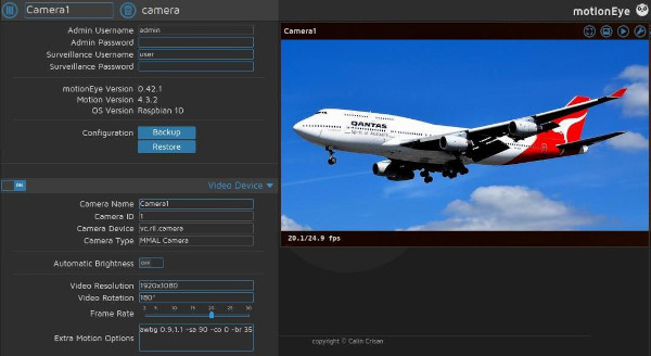
To provide the Node.js-served PTZ application with a video feed, first enable Video Streaming in MotionEye. The available frame-rate and video-quality settings can then be adjusted to suit the application, with the resulting stream available at http://camera.local:8081/.
MotionEye also provides direct access to a JPEG snapshot of the current camera output. This can be viewed in a browser at http://camera.local:8765/picture/1/current/.
If you wish to experiment with video capture triggered by motion detection, there is a slightly non-obvious prerequisite: the Movies tab must first be enabled. Once enabled, Motion Detection can be activated, allowing its various detection and recording parameters to be configured and tested.
PTZ Camera UI
Node.js, running on the Pi Zero 2W, serves the index.html application at http://camera.local:3000/. The interface includes a reference to Motion’s MJPEG stream at http://camera.local:8081/, which is sufficient when the application is being used within the local WLAN. If the interface is to be operated from a remote location, however, this reference must be changed to whatever globally accessible URL you have configured for the camera’s video stream.
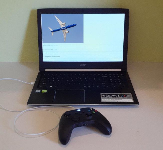
As this was intended only as a pathfinder project, little effort was invested in producing an aesthetically refined user interface. Once a game controller is connected and operational however, the interface provides the essential information required to operate and monitor the system. This includes the camera image, the various locally and remotely reported joystick axes, the absolute positions maintained for the stepper motor axes, and other relevant device-state information.
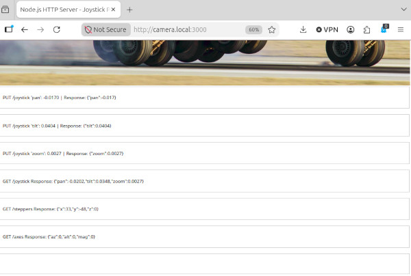
The right-hand joystick’s X and Y axes control pan and tilt speed respectively, with the motor speed varying proportionally according to joystick deflection. The left-hand joystick’s Y axis is assigned to the zoom/ focus function, although this was not connected to the prototype hardware.
I encountered an unexpected difficulty when connecting a recent Microsoft Xbox game controller to Linux Mint. The controller’s joystick and button mappings were presented in a rather unhelpful arrangement, requiring the installation of the rather intimidating xpadneo kernel module to restore the expected axis and button assignments.
Conclusions
The project was an experiment, seeking to determine the merits of replacing the usual Apache webserver, C code, JavaScript and PHP scripting, with the Node.js JavaScript engine and JavaScript. This part of the investigation was a success, and I will be using Node.js for all such WiFi-connected FPV gadgets in future. Node.js v12.22.12 saved a lot of memory space, and is known to be superior in performance in every respect.
The second part of the investigation was less conclusive. Rather than using the conventional I²C link, stepper motor control was implemented using ConfigurableFirmata and its integrated AccelStepper module, communicating with the real-time microcontroller over USB serial. This proved entirely adequate for manual camera positioning, with motor speed varying proportionally with joystick deflection. It did not, however, provide sufficiently smooth, fine-grained positional control for applications such as OpenCV-based motion tracking.
I remain convinced that the Firmata protocol itself is a viable means of communicating with a real-time microcontroller. The limitation was more likely a consequence of the particular way in which I employed ConfigurableFirmata’s AccelStepper class. Its interface is fundamentally intended for a different style of motor control from that required by this application, and the rather unconventional solution described earlier was necessarily a compromise.
However, the Node.js package Firmata.js depends on other outdated Node.js packages, which are difficult to compile on more recent operating systems than Buster, particularly on 64-bit ARM OS’. For that reason, I’m avoiding the future use of Firmata altogether.
For future projects, I expect to return to I²C communication, coupled with dedicated real-time slave peripheral firmware. The previous I²C communication routines may well be revised as a more accessible library implementation, with greater emphasis on comprehensibility, portability, and ease of adoption.

I hope that this project has proved useful to those considering similar technologies for their own work, whether as a practical guide or simply as a source of ideas for further experimentation. At the very least, I hope it has provided a small and worthwhile distraction from the rather troubled state of the world in which we currently find ourselves.
If you are able and so inclined, please consider helping to buy dinner for one of my many beloved street kitties:
paypal.me/RoxbyLaneDumpsterCat 🐾