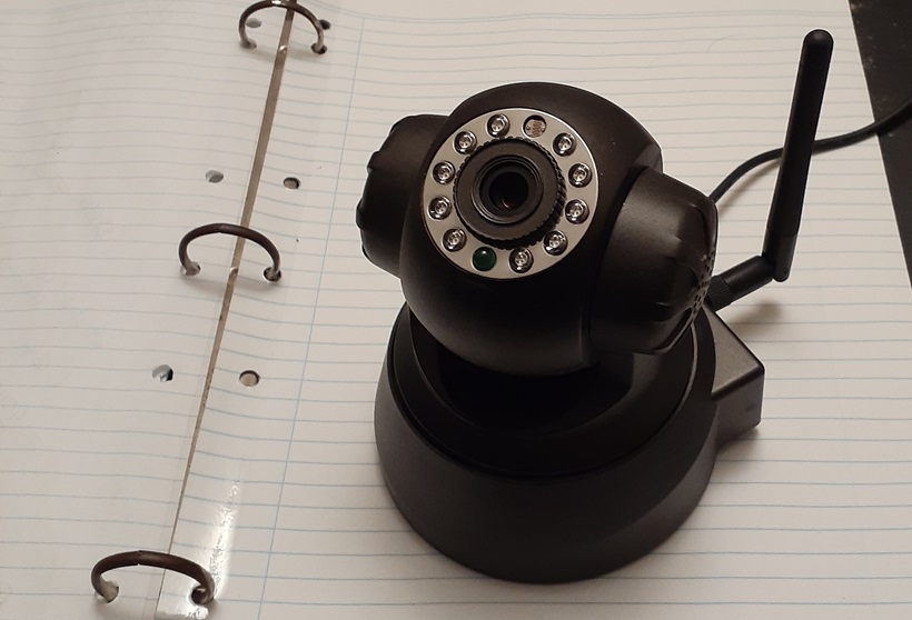
Let’s take an old 640×480 WiFi IP camera, gut it, upgrade the camera to a 5MP USB, and re-animate the PT mechanism with an Arduino Pro Mini, sequencing ULN2003A stepper drivers.
The result will be a tracking mechanism for up to 2 variously telescopic cameras, suitable for image capture, processing and motion tracking experimentation.
Why Fossie had to die.
IP Cameras are usually accompanied by a CGI mechanism with which you can control them using a web browser. There are all manner of setting related to camera tuning, and PT(Z) motion control. As an example:
This was Fossie’s command to raise the PT mechanism one degree. The interface gave full PT stepper motor control, and had a particular setting for x or y motor speeds. Unfortunately, an attempt to change any of these axis traversal rates, has to be followed by an immediate CGI initiated system reset, to be successful. That made effective control, initially via joystick, unviable.
23/10/24
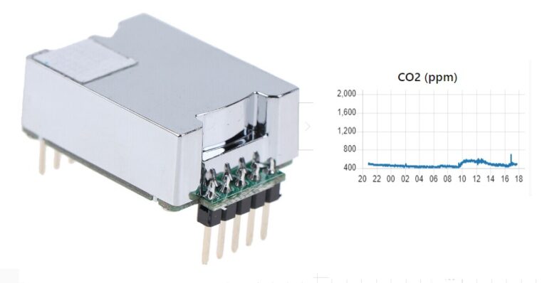
No dissection just yet. From this slightly later model Foscam camera teardown video, I discovered that the two stepper motors are both 28byj-48-5v unipolar, 64:1 reduction gear, 5-wire with XH-5P socket type. They may be driven to between 10RPM and 15RPM, with 4096 half steps or 2048 full steps per revolution.
Time to review the state of the art in off-the-shelf software for stepper motor drive under client system control.
25/10/24
Okay, it looks like the single best option for controlling a stepper motor equipped Arduino remotely, from python (urgh!) or javascript running on a client PC, is ConfigurableFirmata. Paint yourself into a corner with a thing called Telemetrix if you must, but you’ll find the former option your best bet. The latter is only supported by one client library (python), it isn’t at all extensible, and the developer responsible appears to be quite self-important.
1/11/24
Here are some important facts about the two versions of the ConfigurableFirmata Arduino library that you will need to know:
Version 2.x – No support for ESP32, but wide support under client libraries (firmata.js, Johnny-Five, pyfirmata, etc.)
Version 3.x – Support for ESP32, but little support under client libraries, save for the .Net library iot, and possibly some others.
Some ConfigurableFirmata client libraries, their language, and the version of the Firmata protocol they currently support:
firmata.js – JavaScript – Firmata protocol version 2.5.
Johny-Five – JavaScript – Firmata protocol version 2.5 and some 2.6.
pyfirmata – Python – Firmata protocol version 2.1 and some 2.2.
ConfigurableFirmata version numbers mirror the Firmata protocol version they implement. I spent a lot of time learning this the hard way, that protocol support of the chosen client library, must be matched with the appropriate ConfigurableFirmata library version. Also, that the ConfigurableFirmata library must be matched to code derived from it’s version’s ConfigurableFirmata.ino example.
Here’s the list of versions and artefacts I was able to run successfully together on the AT328PB I will use in this project:
Arduino IDE – arduino-ide_2.2.1_Linux_64bit.
ConfigurableFirmata Arduino library version 2.10.1.
Server sketches based on the ConfigurableFirmata.ino example from version 2.10.1.
Node JavaScript client library – Firmata.js current version (1/11/24).
Client javascript implementations based on examples from the current Firmata.js, running in node 12.22.9 on client PC.
You may find the ConfigurableFirmata server sketches produced by the site at firmatabuilder.com useful, be be aware that they should only be built with the 2.10.1 version of the ConfigurableFirmata Arduino library. Get this wrong and you’ll be in a very dark place.
2/11/24
Yep, ConfigurableFirmata and firmata.js do everything they will need to for this project. I’m now intending to use an AT328P microcontroller, rather than the AT328PB that required changes to ConfigurableFirmata’s boards.h file that I couldn’t quite muster.
Trying to get my head around asynchronous programming, the model that javascript on Node.js employs. The book I previously referenced isn’t that comprehensive, so I’m augmenting my erudition with some carefully procured lessons from ChatGPT. What a wonder!
12/12/24
Okay, to control the speed and direction camera’s stepper motors, using a gamepad connected to a remote browser, the chain of events begins at the client. In the index page served by the remote camera, we establish periodic calls to a controlInputsLoop(). This function employs the Gamepad API to access the gamepad, and read it’s inputs. The data is then sent to node.js endpoints, asynchronously, using AJAX (Asynchronous JavaScript and XML) calls. The cycle repeats.
<!DOCTYPEhtml><htmllang="en"><head><metacharset="utf-8"><title>Remote Camera</title></head><body> // Embedable frame sequence URL of MotionEye on Raspbian GNU/Linux 11 (bullseye)<imgsrc="http://192.168.0.114:8765/picture/1/frame/"></body><script>var controlIntervalID;window.addEventListener("gamepadconnected", function() {// Call gamepad control handler every 100ms.controlIntervalID = setInterval('controlInputsLoop()', 100);});window.addEventListener("gamepaddisconnected", function() {clearInterval(controlIntervalID);});function sendCommand(request) {constxhttp = newXMLHttpRequest();// What to do when the response is ready.xhttp.onload = function() {// nothing }// Initialise the GET request with the URL in `request`xhttp.open("GET", request, true);// Send the requestxhttp.send();}function buttonPressed(b) {if (typeof(b) == "object") {// Access true or false pressed property of b. return b.pressed; }returnb == 1.0; // Return true if b numeric 1.0, false otherwise.}controlInputsLoop(){// Returns all connected gamepads.vargamepads = navigator.getGamepads();if (!gamepads)return;// Get the first gamepad.vargp = gamepads[0];if (buttonPressed(gp.buttons[8])) {// System shutdown command.sendCommand("/control/shutdown=1"); }// Acquire control positions between -1.0 to 1.0.varaltitude = gp.axes[3].toFixed(4); // Right Y axisvarazimuth = gp.axes[2].toFixed(4); // Right X axissendCommand("/altitude/" + altitude);sendCommand("/azimuth/" + azimuth);return;}</script></html>
Expect this code to evolve as the project progresses.
Next, we will serve the index page, and create endpoints for each of the data sinks using node.js.
With a recognition of the existing gap, I present this contribution aimed at enhancing the publicly accessible guidelines for laying out and coding Arduino I2C slave devices. This proposal introduces an organizational framework for coding I2C slave peripherals on Arduino, illustrated through a Platformio-based example.
Structure
Using an Atmel328PB microcontroller, we simulate a series of 16-bit peripheral registers, each with an 8-bit address. These registers are programmed akin to standard silicon I2C devices, allowing individual configuration for read-only, write-only, or read-write operations as perceived by the I2C master.
/*****************************************************************************
 *
 *                              Global Variables
 *
 *****************************************************************************/
// An array to store register values
int i2c_registers[I2C_NUM_REGS] = {0};

// I2C session persistent register address
uint8_t registerAddr = 0xFF;
In the development of an I2C slave application, peripheral functionality must be implemented through data source and data sink operations, skillfully integrated with the aforementioned emulated device registers.
In scenarios demanding highly efficient application code execution, integration occurs within the I2C interrupt service context. These application operations are executed dynamically during active I2C communication. However, integrating time-consuming application operations here can potentially delay I2C timing to a degree that compromises standards compliance, resulting in communication failures.
To mitigate this risk, in cases where application code runs slower, linkage between data source/sink operations and emulated peripheral registers occurs outside the I2C service interrupt context, typically within or under the task loop scope. Despite this approach, simultaneous access to emulated registers can occur, due to I2C ISR service routine triggering, leading to data integrity issues.
To ensure robustness, a pair of interrupt-suspending memory access macros is provided. These macros guarantee atomicity during peripheral register data manipulation within the task loop, thereby preventing potential corruption
I2C Call-back Functions
During program setup, the I2C bus under configuration, is assigned a device address, and call-back routines for the service of wired I2C bus transactions. When an I2C-inbound write occurs, data is consumed and/ or is stored in a register, with code inside the receiveEvent() callback. When an I2C-inbound read occurs, data is application generated, or is retrieved from a register, inside the requestEvent() ISR.
  Wire.begin(I2C_ADDRESS);      // Initialize I2C communication as a slave
  Wire.onReceive(receiveEvent); // Register the receive event handler
  Wire.onRequest(requestEvent); // Register the request event handler
The unpopulated receiveEvent() call-back
An unpopulated receiveEvent() ISR services wired I2C register storage instructions. Not yet linked to any application functionality, it merely provides write access to peripheral register memory.
/*****************************************************************************
 *
 *                               receiveEvent()
 *
 *****************************************************************************/
// Event handler for receiving data from the master, to write to a register
void receiveEvent(int numBytes)
{
  // Read the requested register address
  registerAddr = Wire.read();

  if (numBytes == 3)
  {
    // Read the data to write
    uint16_t value = Wire.read() ;        // value LSB
    value |= Wire.read() << 8;            // value MSB

    switch (registerAddr)
    {
      // Comment-out any read-only registers to prevent master write
      case I2C_REG_0:
      case I2C_REG_1:
      case I2C_REG_2:
      case I2C_REG_3:
      case I2C_REG_4:
      case I2C_REG_5:
      case I2C_REG_6:
      case I2C_REG_7:
      {
        i2c_registers[registerAddr] = value;
        break;
      }
      default: return;
    }

    I2C_WRITE_DEBUG(registerAddr, value)
  }
}
The unpopulated requestEvent() call-back
An unpopulated requestEvent() ISR services wired I2C register retrieval instructions. Not yet linked to any application functionality, it merely provides read access to peripheral register memory.
/*****************************************************************************
 *
 *                               requestEvent()
 *
 *****************************************************************************/
// Event handler for responding to requests for register contents, from the master
void requestEvent()
{
  uint16_t value = 0;

  switch (registerAddr)
  {
    // Comment out any write-only registers to prevent master read
    case I2C_REG_0:
    case I2C_REG_1:
    case I2C_REG_2:
    case I2C_REG_3:
    case I2C_REG_4:
    case I2C_REG_5:
    case I2C_REG_6:
    case I2C_REG_7:
    {
      value = i2c_registers[registerAddr];
      break;
    }
    default:
      return;
  }

  // Send the data read from
  Wire.write(value & 0xFF); // send LSB
  Wire.write(value >> 8);   // send MSB

  I2C_READ_DEBUG(registerAddr, value);

  return;
}
Read-ability and write-ability
So, we may see from the above, in the unpopulated ISR pair, an I2C master has the ability to write a value to one of a number of memory-only registers, and then read it back from there verbatim. We’ll see later, when we come to adding applications, such simultaneous read-ability and write-ability may not be desirable.
To make a peripheral register read-only, we remove the receiveEvent() ISRs ability to service peripheral register write requests. We do this by commenting-out service routine switch cases that involve the register.
void receiveEvent(int numBytes)
{

...

    switch (registerAddr)
    {
      // Comment out any read-only registers to prevent master write
      case I2C_REG_0:
      //case I2C_REG_1:  // Make register 1 read-only
      case I2C_REG_2:
      case I2C_REG_3:
      case I2C_REG_4:
      case I2C_REG_5:
      case I2C_REG_6:
      case I2C_REG_7:
      {
        i2c_registers[registerAddr] = value;
        break;
      }
      default: return;
    }

...
To make a peripheral register write-only, we remove the requestEvent() ISRs ability to service peripheral register read requests. Again, we do this by commenting-out service routine switch cases that involve the register.
void requestEvent()
{

...

  switch (registerAddr)
  {
    // Comment out any write-only registers to prevent master read
    case I2C_REG_0:
    case I2C_REG_1:
    // case I2C_REG_2:  // Make register 2 write-only
    case I2C_REG_3:
    case I2C_REG_4:
    case I2C_REG_5:
    case I2C_REG_6:
    case I2C_REG_7:
    {
      value = i2c_registers[registerAddr];
      break;
    }
    default:
      return;
  }

...
Application linkage inside loop()
Now that we have our peripheral registers configured, variously as read and write, read-only, or write-only, we come to linking these to application code. This involves the data sink and data source routines, that you will develop for your peripheral.
Remember, all access to peripheral registers outside the I2C interrupt service context, must employ the atomic register access macros, I2C_ATOMIC_REG_RD() and I2C_ATOMIC_REG_WR(). Again, this is vital to prevent the data corruption that occurs, when I2C ISRs are invoked, during peripheral register access. The macros momentarily ‘lock-out’ the ISRs.
/************************************************************************
 *
 *                                loop()
 *
 ************************************************************************/
void loop()
{
  {
    uint16_t value = 0;

    // Read adc, and atomically save val in read-only slave register 1
    value = myadc_read();
    // i2c_registers[I2C_REG_1] = value; <- not atomic, instead...
    I2C_ATOMIC_REG_WR(i2c_registers[I2C_REG_1], value);

    // Retrieve contents of slave register 0 atomically, and consume
    // value = i2c_registers[I2C_REG_0]; <- not atomic, instead...
    I2C_ATOMIC_REG_RD(value, i2c_registers[I2C_REG_0]);
    myservo_set_pos(value);
  }

  // Other application tasks.

}
In the above, we see that a logically read-only peripheral register, I2C_REG_1, is fed samples from an onboard ADC, using an application call to myadc_read(). A remotely wired, I2C master may read the stored register data, with calls such as wiringPi’s wiringPiI2CReadReg16().
As well, above, we have an either read and write, or write-only configured peripheral register, I2C_REG_0, feeding position data to an attached servo. It does this via an application call to myservo_set_pos(). A remotely wired, I2C master may write the servo position data, with calls such as wiringPi’s wiringPiI2CWriteReg16().
On-demand, vs polled register access
The above mentioned approach for linking application data sink and source functionality, to underlying peripheral register memory, from outside I2C ISR service context, can be wasteful. Significant cpu cycles are consumed, in the application either constantly polling peripheral registers for incoming data, or frequently updating peripheral registers for fresh outgoing data.
To increase application efficiency, an alternate user code linkage solution exists, for on-demand exchange of data with peripheral registers. This involves application data source and data sink function calls, from within I2C ISR service context.
As mentioned previously, application calls made inside either of the I2C ISR call-backs, must be very brief, so as not to disrupt wired I2C communication. Between the servo and ADC application calls dealt with previously, only the myservo_set_pos() call is suitable. The myadc_read() function involves lengthy over-sampling, and any attempt to link it ‘on-demand’, from within an ISR, will break associated I2C transactions.
Application linkage inside the I2C ISRs
Here we examine the alternative approach to linking an I2C slave peripheral’s servo position. Data is exchanged only when requested to be, by a wired I2C bus transaction. The I2C receiveEvent() ISR handles incoming data, and we merely write that ‘value’ data to the servo, using the necessarily fast myservo_set_pos() application call.
void receiveEvent(int numBytes)
{

...

    switch (registerAddr)
    {
      // Comment out any read-only registers to prevent master write
      case I2C_REG_0:
      {
        myservo_set_pos(value);
        i2c_registers[registerAddr] = value;
        break;
      }
      //case I2C_REG_1:  // Read-only
      case I2C_REG_2:
      case I2C_REG_3:
      case I2C_REG_4:
      case I2C_REG_5:
      case I2C_REG_6:
      case I2C_REG_7:
      {
        i2c_registers[registerAddr] = value;
        break;
      }
      default: return;
    }

    I2C_WRITE_DEBUG(registerAddr, value)
  }
}

...
In this case, we have chosen to make the servo peripheral register both readable, and writeable. To accomplish this, we must also store the incoming data in the underlying peripheral register, as shown above.
In the case where we wanted to make the application’s servo peripheral register write only, we would not store the incoming position data in any underlying peripheral register, or, at the very least, make the underlying register write only. This is again accomplished, by commenting-out the appropriate switch statement case, inside the requestEvent() ISR.
void requestEvent()
{

...

  switch (registerAddr)
  {
    // Comment out any write-only registers to prevent master read
    //case I2C_REG_0:  // Make servo register 0 write-only
    case I2C_REG_1:
    case I2C_REG_2:
    case I2C_REG_3:
    case I2C_REG_4:
    case I2C_REG_5:
    case I2C_REG_6:
    case I2C_REG_7:
    {
      value = i2c_registers[registerAddr];
      break;
    }
    default:
      return;
  }

...
For the final case, we examine how outgoing application data may be linked to peripheral register requests, on-demand, from within I2C ISR context. For this, we will read an attached switch, with an imaginary application call, myswitch_get_posn(). We know that the call will be fast enough not to break wired I2C communication, and that logically the operation must be read-only.
The I2C requestEvent() ISR handles outgoing data, and we merely service a request for the switch position, with data from the myswitch_get_posn() application call.
void requestEvent()
{

...

  switch (registerAddr)
  {
    // Comment out any write-only registers to prevent master read
    case I2C_REG_2:
    {
      value = myswitch_get_posn();
      break;
    }
    case I2C_REG_0:
    case I2C_REG_1:
    case I2C_REG_3:
    case I2C_REG_4:
    case I2C_REG_5:
    case I2C_REG_6:
    case I2C_REG_7:
    {
      value = i2c_registers[registerAddr];
      break;
    }
    default:
      return;
  }

...
As seen above, the switch peripheral register is logically read only, so stored peripheral register memory is not involved. To disable any attempt to write a peripheral register, making it read only, we comment-out it’s associated entry in the receiveEvent() I2C ISR.
void requestEvent()
{

...

  switch (registerAddr)
  {
    // Comment out any write-only registers to prevent master read
    case I2C_REG_0:
    case I2C_REG_1:
    // case I2C_REG_2:  // Make switch register 2 write-only
    case I2C_REG_3:
    case I2C_REG_4:
    case I2C_REG_5:
    case I2C_REG_6:
    case I2C_REG_7:
    {
      value = i2c_registers[registerAddr];
      break;
    }
    default:
      return;
  }

...
Improving polled access efficiency
/************************************************************************
 *
 *                                loop()
 *
 ************************************************************************/
void loop()
{
  {
    uint16_t value = 0;

    if (myservo_changed())
    {
      // Retrieve contents of slave register 0 atomically, and consume
      I2C_ATOMIC_REG_RD(value, i2c_registers[I2C_REG_0]);
      myservo_set_changed(0);

      // From here on, receiveEvent() ISR can take new register data,
      // and the snapshot 'value' can be processed, even if exhaustively
      myservo_set_pos(value);
    }
  }

  // Other application tasks.

}
void receiveEvent(int numBytes)
{

...

    switch (registerAddr)
    {
      // Comment out any read-only registers to prevent master write
      case I2C_REG_0:
      {
        i2c_registers[registerAddr] = value;
        myservo_set_changed(1);
        break;
      }
      case I2C_REG_1:
      case I2C_REG_2:
      case I2C_REG_3:
      case I2C_REG_4:
      case I2C_REG_5:
      case I2C_REG_6:
      case I2C_REG_7:
      {
        i2c_registers[registerAddr] = value;
        break;
      }
      default: return;
    }

    I2C_WRITE_DEBUG(registerAddr, value)
  }
}

...
Well, that’s how the I2C slave peripheral model works, how to constrain access to it’s underlying peripheral registers, and how to link-in application code. Application linkage methods were shown, both by polling inside loop(), and by on-demand calls inside ISR context.
Just remember to keep application calls short inside the ISRs, and to use atomic register access macros outside them.
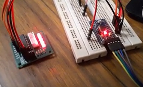
Associated Files:
The attached Arduino I2C slave demonstration code for this example, runs on an AT328PB. It reads the position of an ADC-connected potentiometer, and stores this data in a 16-bit I2C register numbered 1. It also reads data in a 16-bit I2C register numbered 0, and sets the corresponding position of an attached servo.
Example C code for a wiringPi-installed, Raspberry Pi master is also provided, which remotely reads the potentiometer value, and writes a proportionate value back to the I2C slave peripheral’s servo control register.
Demonstration code, of the suggested organisational paradigm, for an Arduino I2C slave peripheral. I2C_slave_model.zip
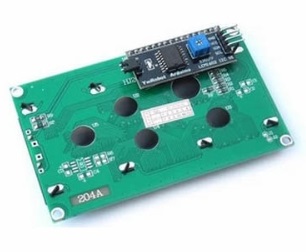
The LiquidCrystal_I2C library is a modified version of the standard LiquidCrystal library as found on the Arduino website.
HD44780 controlled LCD, fitted with Chinese PCF8574 I2C backpack.
This library is intended to be used when a parallel HD44780 compatible LCD is controlled over I2C using a Chinese PCF8574 extender, as sold on eBay.
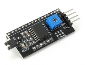
Chinese PCF8574 I2C to parallel LCD backpack.
Be aware that the Chinese PCF8574 extender is available in two versions, the PCF8574 and the PCF8574A, the only difference between the two is the I2C base address. See the documentation for details.