
I detail the make of WiFi Robots, with first person video, sensory feedback, and actuator control, from ‘toy hacked’ remote control toys.
WiFi FPV Robot 1
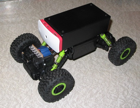
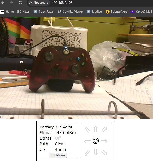
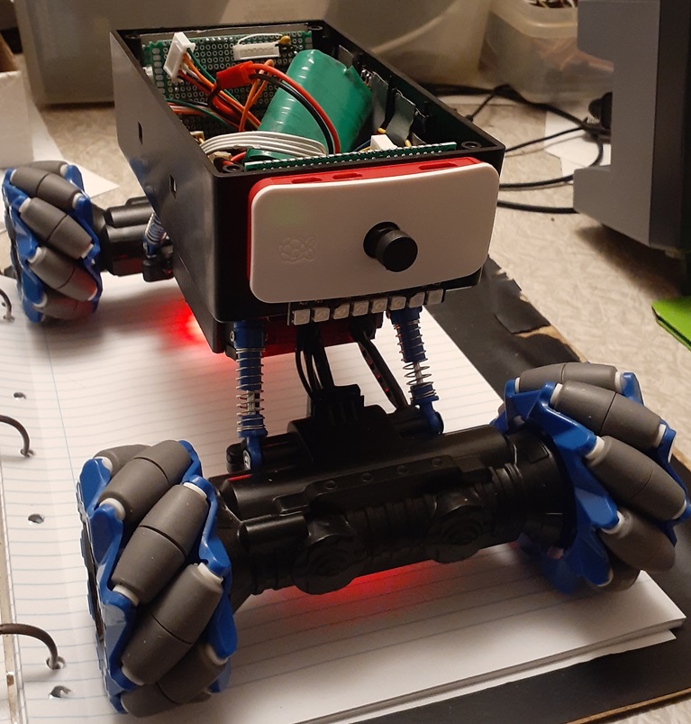
WiFi FPV Robot 1, featured above, is built upon a 2.4GHz RC Rock crawler chassis. The fitted Raspberry Pi Zero W streams video to an HTTP browser session, from which the operator can gain status feedback, and control motors and lights with a game controller.
The project was unique, in that it successfully employed dc brushed motor Back-EMF measurements, for fine motor control. The inbuilt Arduino 328P Nano, is tasked with motor feedback sampling and PID control, motor PWM outputs, as well as lighting control, status assessment and reporting.
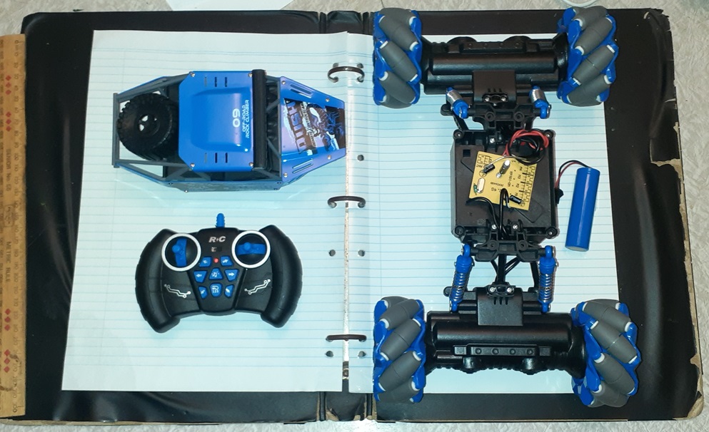
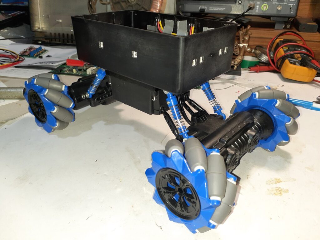
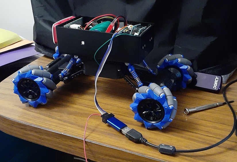
WiFi FPV Robot 2 (WIP)

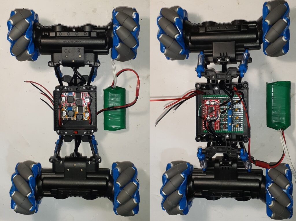
The plan is to acquire a mecanum wheeled version of the un-branded RC Rock Crawler used in V1, and convert it using many of the same techniques and technologies employed previously.
The updated mecanum rc toy runs a AUD$55 investment, though?
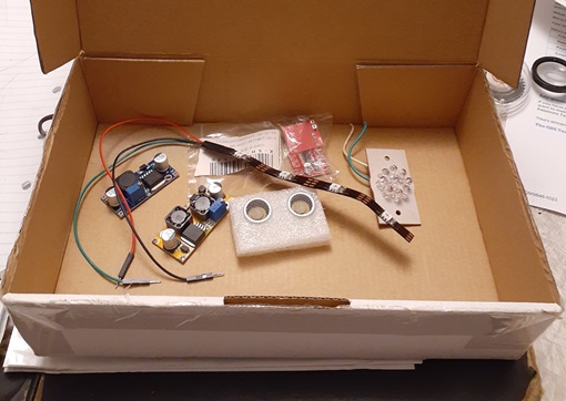
11/04/2024 – Component accumulation ensues…
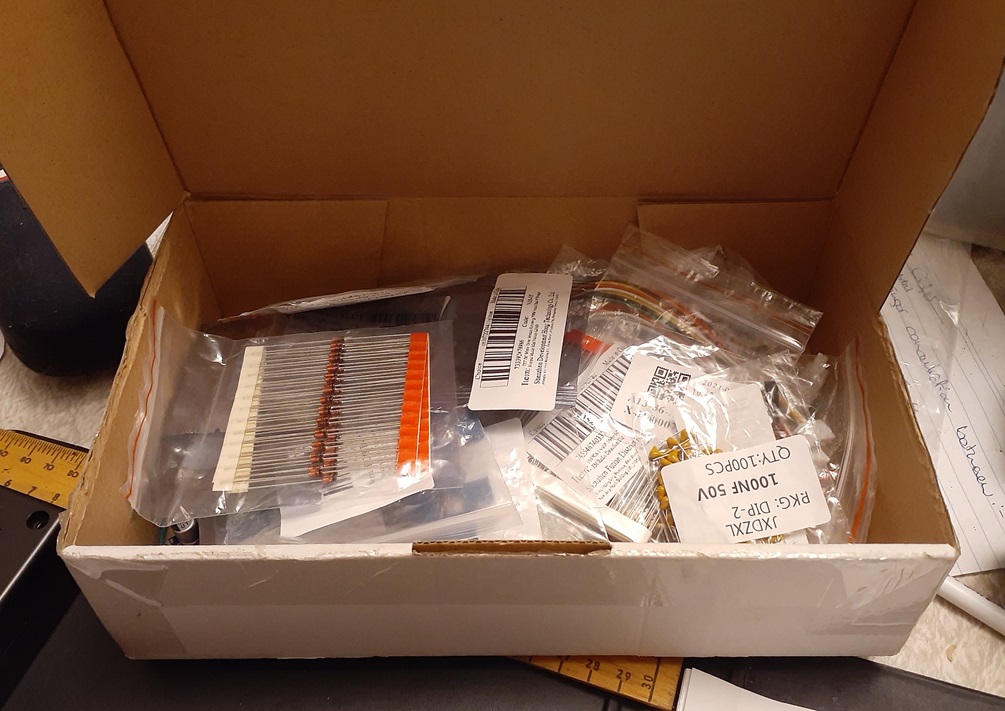
22/04/24 – Parts still amassing.
ARDUINO COMPONENT
Interested in Raspberry Pi and Arduino robotics? Why not check-out my Arduino I2C Slave Peripheral Paradigm? There’s a brief write-up on how to use it, as well as sample code to download.
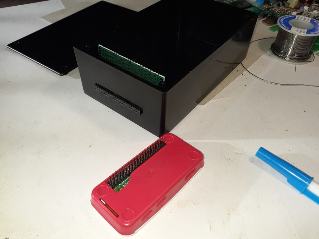
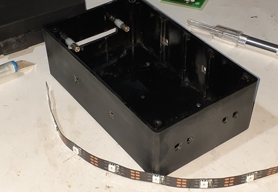
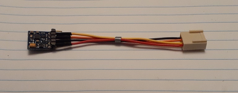
23/04/24 – The front connector for a Raspberry Pi Zero 2W.
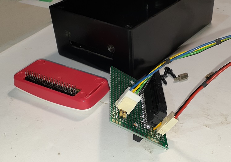
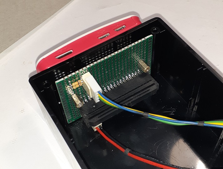
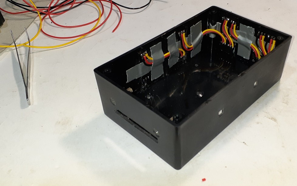
24/04/24 – That’s I2C and power to the Pi Zero 2W, and an unpopulated IDC header to wire any remaining Pi pin, if ever required.
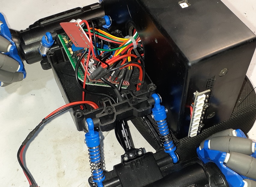
26/04/24 – The autopsy commences. I will measure motor currents first, before gutting, then build the electronics bay up large enough to accommodate PSUs, H-Bridges, and feedback signal conditioning. – Loaded motors current was ~2A or more. I’ll be splitting that between dual 1.5A supplies. The remaining half ampere on each, is exhausted by CPU and microcontroller power on one converter, and by more extensive lighting on the other.
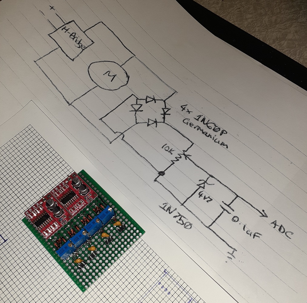
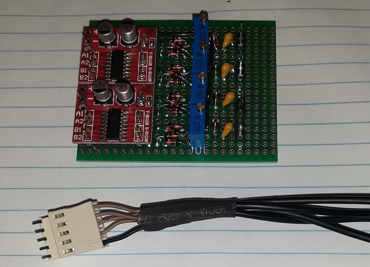
27/04/24 – Four motors, means 4 signal conditioner circuits. They rectify, filter, scale and clip, motor back EMF signals for ADC conversion. This is the signal we use to control engine power, using PIDs. Perf board turned out to be a good choice, and the whole board was done in 2 hours, or so. Used less space than budgeted.
28/04/24 – 65-degree field of view, 5Mp OV5647 camera, gets a 120-degree FOV lens upgrade, courtesy of a cheap OV2640 donor camera. On the second attempt, I sanded the square flange right off the donor’s lens mounting ring. With SuperGlue, I tacked it to the old lens mount, where it’s lens ring had been sanded away. A final skin of epoxy, secures the 2 lens fixtures together, as well to the camera image sensor. The result was flawless.- I couldn’t find a wide angle lens equipped camera, for my Pi Zero 2W’s in-housing v2 camera, so I made one…hacking defined.
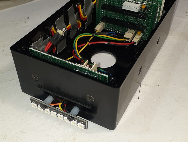
28/04/24 – Twin 1.5A Buck Boost power converters installed in the battery compartment. Loads of room for the H-Bridge and signal conditioner above.
ARDUINO COMPONENT
I’ve just finished the Arduino I2C slave peripheral code, which I’ll be using soon, and you can see the full write-up, and download the demo source over here.
As a foundation upon which to build register-oriented, I2C applications. These, typically in the control and data acquisition genre. The solution I provide in ‘Arduino I2C Slave Peripheral Paradigm’, is a good choice to build your application code over. The user implements both data source and data sink application functions, and link these to the underlying, emulated register set. The methods are fully documented, and the code has been ‘hardened’, during intense peer review.
Side and Rear Lights
30/04/24 – Marking, then carving up the enclosure; 8 square holes, mounting and wiring of 8 LEDs.
More WS2812 lights coming, for a total around 300mA. Adding in the original toy’s underbody lighting, will draw another 30+mA, as they’re being overdriven.
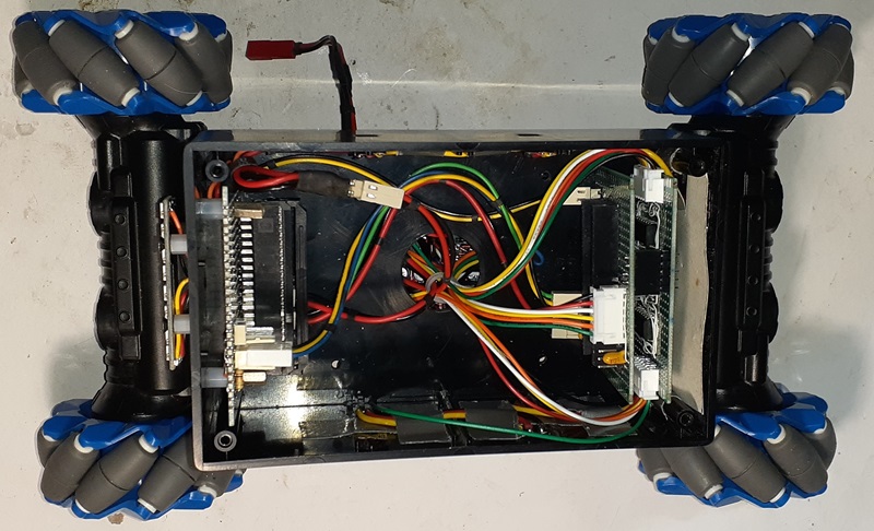
Body on Chassis
30/04/24 – Saw-milled dowel from a hardwood plank, to make the body/ chassis interstitial rails. Drill press used to bore the 4mm holes.
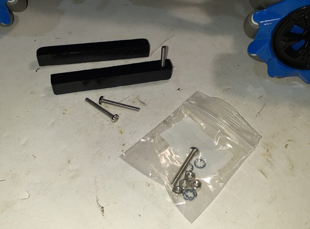
Everything fits, some polishing to do.
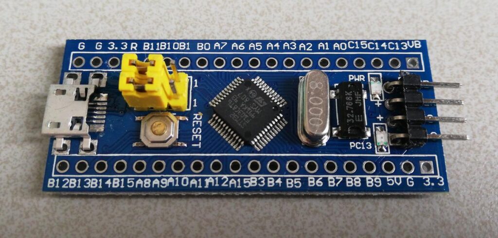
STM32F103C8T6 Blue Pill
I’ve been using an AT328PB microcontroller for development up to this point. It has decided to refuse to fully connect and program now, so I’m done with that device. It was never really suited to running 8 PWMs, and was looking like too much bother, anyhow.
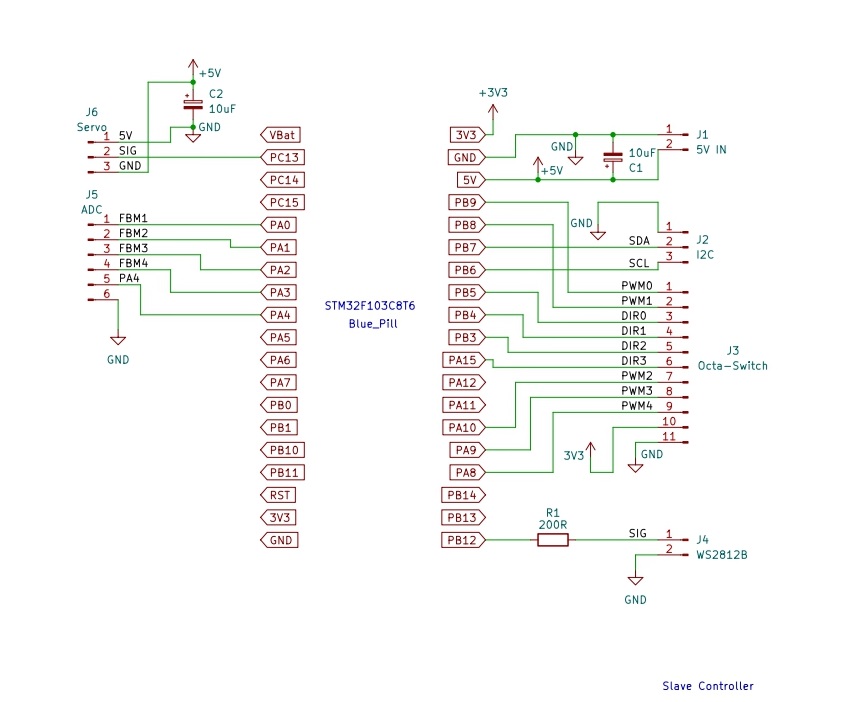
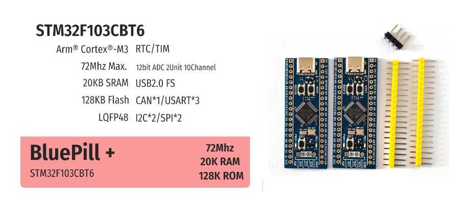
So, now I’m looking at STM32F103C8T6 Blue Pill board, making sure which pins are available to run things like PWMs, DACs, etc.
Blue Pills were once a pain to work with, though ST’s USB Bootloader, has made it pleasure (but a setup hurdle).
15 PWM outputs!!! Buckets of CPU to run the 4 PID loops. Hope everything else works out.
Slave development and wiring
2/05/24 – Got code for an I2C slave with servo and potentiometer working. Different Servo library. Got Neopixel drive working, with a different STM32 library.
Will try to bring the full set of peripheral hardware up on the Blue Pill later tonight. So far, it’s looking good for application fit.

3/05/24 – Can now get 8 PWM outputs with Arduino calls, but only at 1kHz, and only on 8 of the 10 ADC inputs. We need 5 ADC inputs, so have to setup alternate PWM hardware myself.
Now, can get 5 PWM outputs, from 7 in non ADC group, to work. 2 taken by I2C. Need to figure out how to drive 4 reversible motors, using only 1 PWM for each. That’s extra logic to design and build.
Neopixel module looks great, but makes my I2C unstable. !
Extra logic
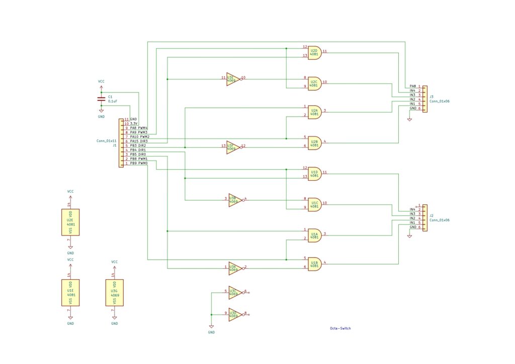
To drive the 8 H-Bridge motor inputs, with just 4 PWM outputs, we need some extra logic. Octal gated switches, to be precise.
Oh, how we love to hand wire daughter boards.
Slave Motherboard gets a Daughter
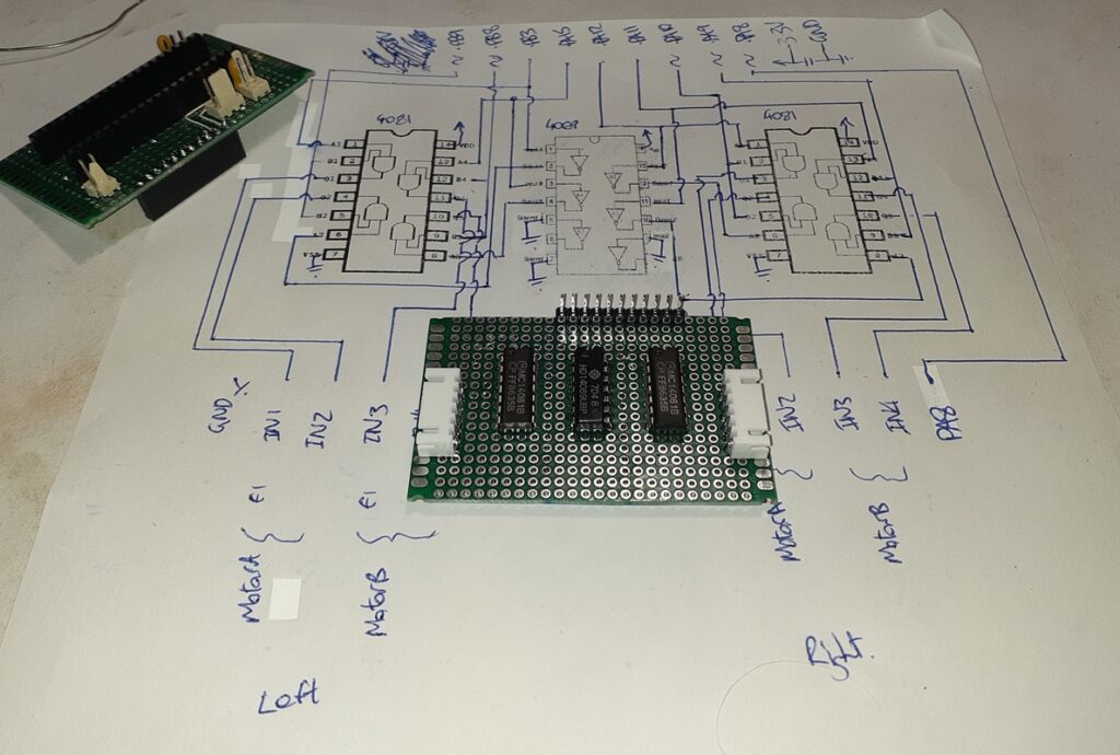
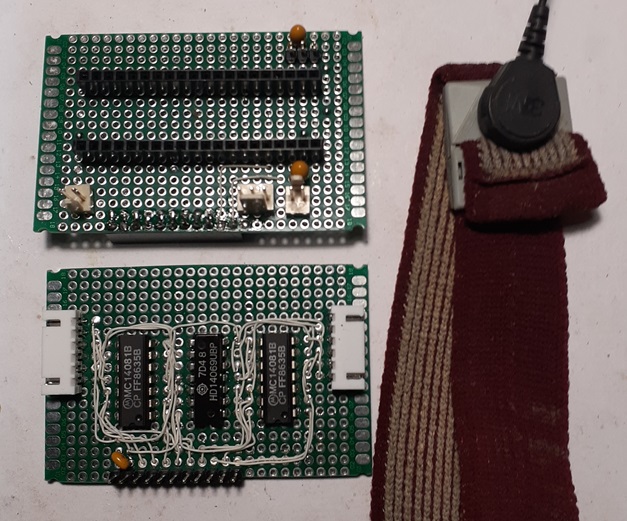
5/05/24 – Have the Octa-Switch tested, debugged and fully documented. ChatGPT seems to think that it should be called a quad duo-switch. Whicheither!
7/05/2024 – Got the Slave Controller’s Motherboard likely finalised, and then documented.
7/05/24 – FastLED refuses to work on the Blue Pill. Might be able to fix AdaFruit’s NeoPixel code, and stop it crashing I2C, but my STM32F103C8T6 Blue Pill Board has gone to heaven. Replacement board will have double flash size, and get here in ~12-days. Kind of a spanner, but I can re-order loads of other tasks.
8/05/24 – Blue Pill remains intermittent. WS8212 Neopixel for light bar arrived. Tested, and fortunately compatible with other LEDs. Wired-up, so that’s just the H-Bridge/ signal conditioner PCB to finish wiring.
All basic internal wiring complete, enough to run CPUs, motors and lights. Won’t power-up, so some tracing to do. Back to the dodgy bootloader problem first. Several bootloader options, dunno which is best.
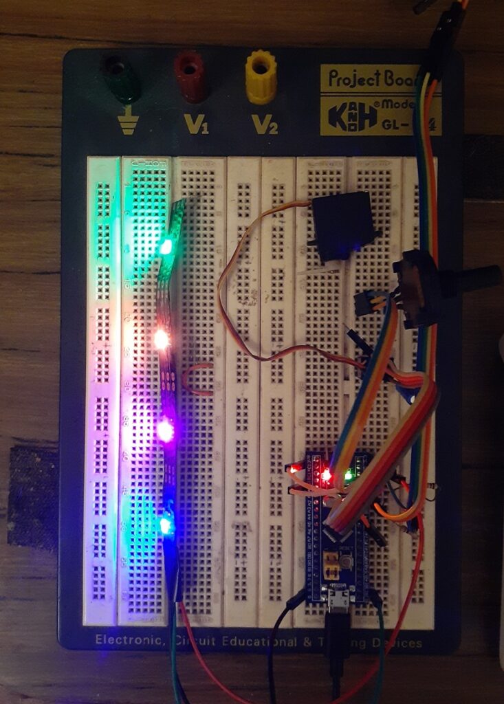
9/05/24 – Given up on USB bootloaders, in favour of an ST-Link v2 USB debugger. The USB debugger was a real boon, but failed to connect reliably for programming.
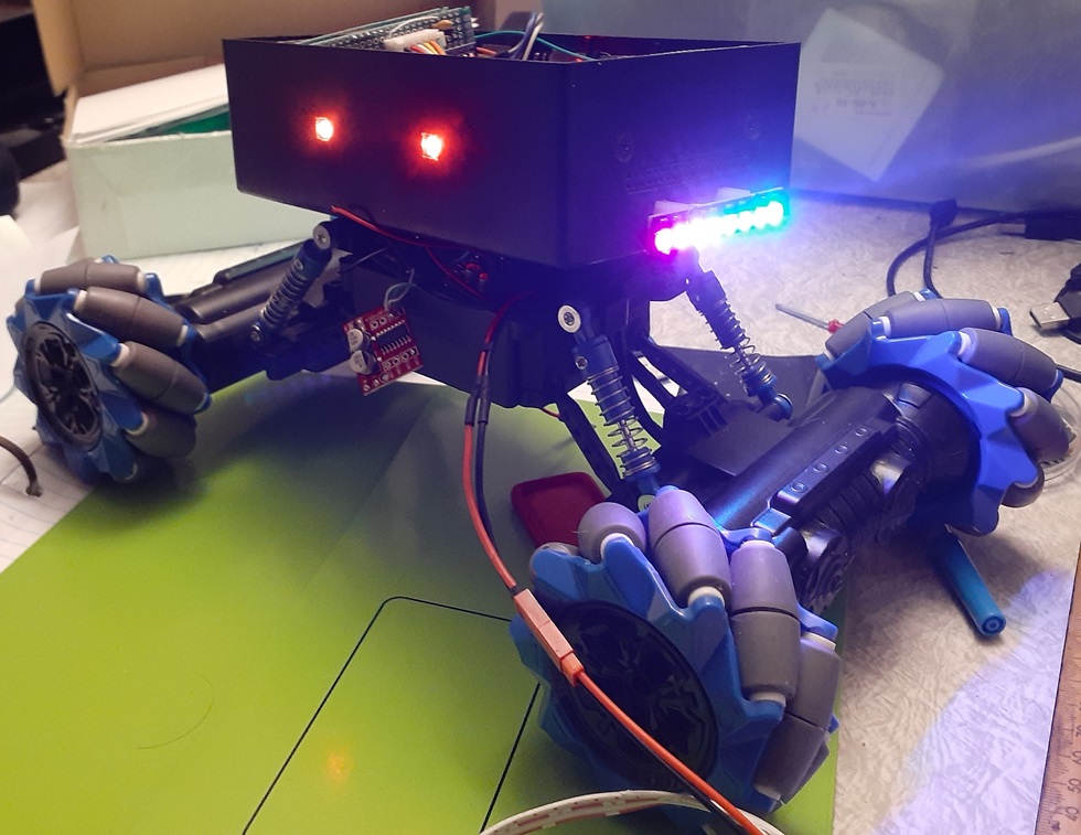
First light from all 16 NeoPixels, photo does no justice.
11/05/24 – Sick as a dog.
12/05/24 – Extant Blue Pill board has developed a short from 3.3v to GND. Toast. New Blue Pill+ might arrive on Friday. I’ll be very interested to see how the USB Bootloader for a high density F103CB device works. Debugger is better, but hid device is just so easy.
13/05/24 – Basic rover hardware tested and working. Will be slow-going until replacement Blue Pill+ arrives. More care not to reverse bias the LDO on the new one.
HMC5883L
Adding this HMC5883L magnetometer early in the build, as it will be used to help control mecanum yaw motion. I’ve previously written a Compass module in C, that gives accurate compass degrees, either planar, or from a known tilt angle. We’ll use the planar compass routine here.
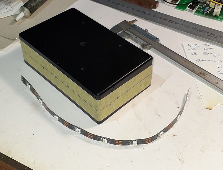
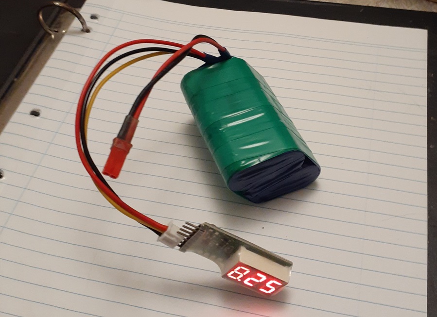
6Ah 8.4V Battery
~50Wh, 2S2P, 4 x 18650 3000mAh 15A NMC LiPo, slanted to reduce height.
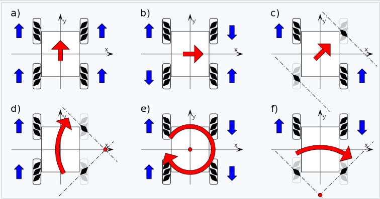
14/05/24 – 3-motors and 1 PID loop in the first WiFi Robot was tricky enough. Now there are 4-motors and 4 PID control loops to code. All whilst getting one’s head around the permutations of this:
Getting Arduino AVR Disassembly with Platformio
You can get a cpp-source-interleaved disassembly listing, when compiling for Arduino AVR with Platformio.
...

void loop()
{
  // Read adc and save result in read-only slave register 1
  i2c_registers[I2C_REG_1] = myadc_read();
     cc2:	0e 94 46 06 	call	0xc8c	; 0xc8c <_Z10myadc_readv>
     cc6:	90 93 21 01 	sts	0x0121, r25	; 0x800121 <i2c_registers+0x3>
     cca:	80 93 20 01 	sts	0x0120, r24	; 0x800120 <i2c_registers+0x2>

...
15/05/24 – Have ‘roughed-out’ control for 4 PID motor drivers, each with stall recovery, FAA lighting control, and battery voltage monitor.
Code structure needs much work, before dressing-up for presentation. Very productive coding session, lots of flow.

On-track for Blue Pill+ delivery on Friday, 2-days hence. If not, then Monday.
Time to ride=-🚴
16/05/24 – Auspost says the Blue Pill+ will be delivered today. Better get cracking and properly structure the motor driver, light control and voltage sensing solution.
Later:
Blue Pill+ arrived quite early. USB HID Bootloader is just as rubbish, so straight back to the debugger for programming. Plus variant pinout turns out to be different for 1 power pin. It shorted the 5V, when I plugged it into the hardware. Also, onboard indicator LED also changed.
17/05/24 – All 4 PWM motor drivers working, with motor back EMF feedback and PID control for each. FAA LEDs also working. Restructure complete. Tiny bit of optimisation, then dress-up for presentation, and we can move-on to mecanum moves.
Taking a slow day, as pooped from last few days frantic coding.
18/04/24 – Basic PID tune in place, stall detection debugged and roughly attuned.
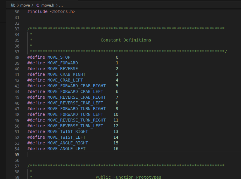
Things are starting to come together, with mecanum motion motor patterns:
19/05/24 – Come to actually use that I2C slave code library you spent weeks agonising over every detail of, and you find it doesn’t work, still?!?!
As it looks, this could take a bit. Problem is with the Arduino Wire library, running on STM32 hardware.
Later: Cracked it. Default 100kHz Wire functionality problematic. Getting both master and slave up at 400kHz bothersome, but mostly successful. Time for a reward.🚴♂️
20/05/24 – All but 1 bug eliminated from I2C slave code. Needed something to command it, so skipped-ahead and re-wrote the I2C master code from first WiFi FPV Robot, so it now issues new moves and instructions. Will use it to debug the slave code tomorrow, when both the robot’s batteries, as well my own, are recharged.
Actually quite close to the end result, of basic FPV interaction. Just some JavaScript and PHP for the server to be re-written. Not bothering with On-screen visual feedback of controller inputs this time, as the mecanum movements don’t translate. That will make things far easier.
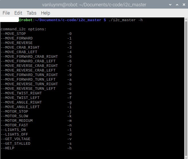
21/05/24 – Busy debugging the i2c part of the slave. Responds to most of the commands depicted above, yet won’t run any motors.
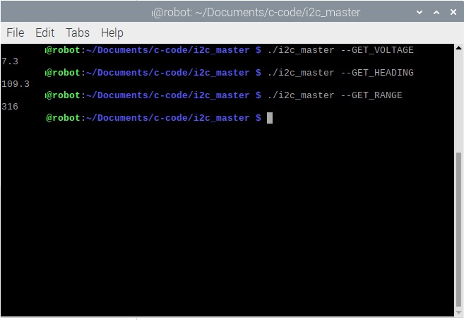
Later: Have the full i2c link working. On the master Raspberry Pi, you issue a command like i2c_master –LIGHTS_ON, and the Arduino slave now responds appropriately.
I2C comm link will be complete, after the servo driver is integrated into the slave, and a means to set it’s value is inserted into the i2c_master program.
Later again: Disaster! A timer conflict, between Arduino PWM outputs, and their Servo library.
22/05/24 – Bogged-down trying to find a solution to drive a servo off timer 2. Can’t get any of the public servo libraries to work. Not above writing my own servo driver, but then find public timer libraries are also shit. Okay, not above writing my own timer code, too!
24/05/24 – Still bogged, trying to get STM32CubeMX projects to compile on Platformio. Working toward a Timer library for Arduino. Drama downloading ST software, won’t be resolved today.
25/05/24 – Have the timer working as an STM32CubeMX project under Platformio (Gasp!). Now, to figure-out how to run just the timer code, as an Arduino library.
26/05/24 – Finally! As an Arduino library, using the Arduino STM32 HardwareTimer library, may I present, An up to 8 Positive-Pulse PWM Servo Driver.
Okay, 8 Positive-Pulse PWM Servo Driver library for Arduino, now integrated with I2C control of remaining mecanum robot functionality. Works great. Login to the Raspberry Pi 2W and type ‘i2c_master –SET_SERVO 127’, and hear the tiny 9g servo zip to it’s centre. No discernible latency, whatsoever!
Later: Fixed a sequencing error in the lighting system, and added a low-pass filter to the stream of battery voltage measurements. The battery voltage readings were very noisy when all four mecanum motors ran, and adding a couple of 1uF ceramics across the ADC input didn’t help much.
28/05/24 – Have build drivers for, and debugged both the HMC5833L magnetometer, and the VL53L1 time of flight distance sensor. Both of these have been integrated into the i2c_master program, that runs on the Pi Zero 2W. The three nodes on the Pi Zero 2W’s mastered i2c network are, the STM32 acting as real-time dog’s-body, the TOF distance sensor, and the magnetometer compass.
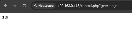
Now, we need to expand and modify, the PHP file that calls the i2c_master program, with parameters based on the webserver PHP file’s HTTP GET request.
Later:
30/05/24 – Whilst prototyping new ideas for the WiFi FPV Robot’s main webpage, we’ve discovered an issue.
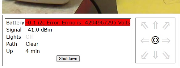
i2c runs fine for a time, but then there’s the inevitable crash. The Pi Zero 2W hosted i2c_master runs afresh every repeated invocation, so that’s not primarily suspicious.
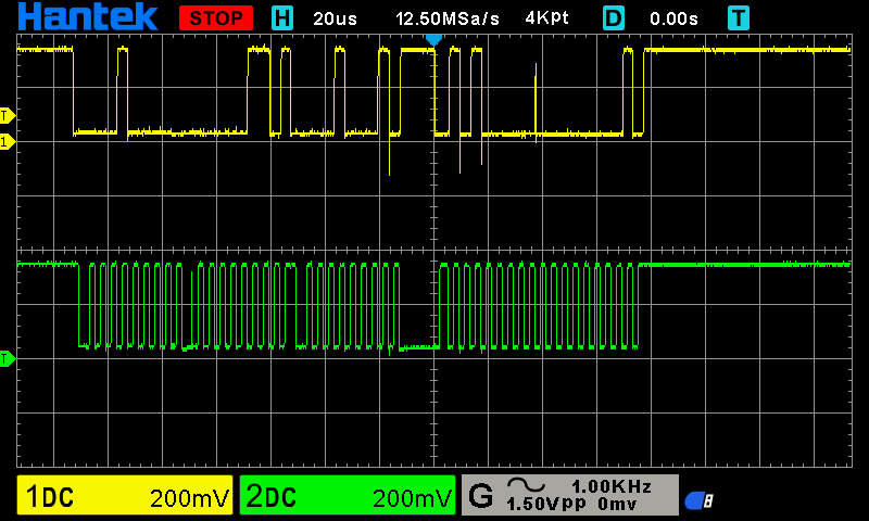
The error appears to occur for voltage retrieval, with associated voltage reports of -0.1, and 0.0. Everything stops as far as i2c comms goes, and there’s a strange pattern on the i2c lines:
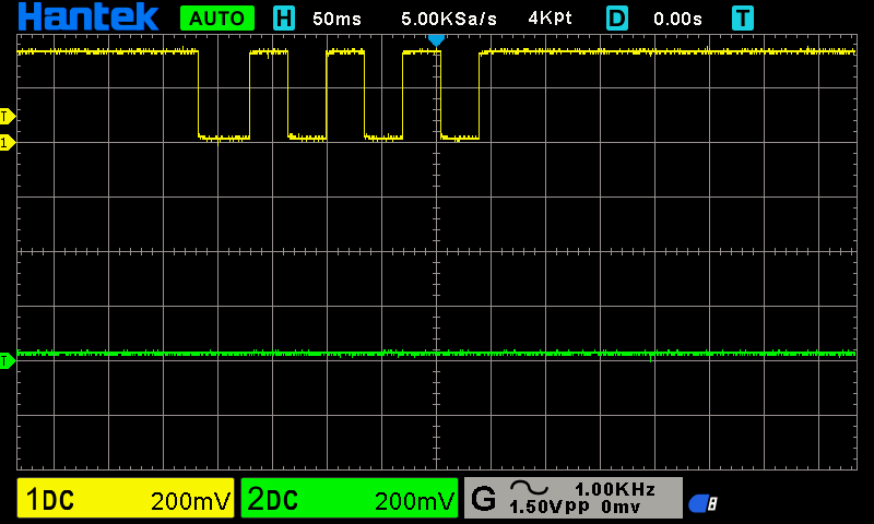
So, which is it? The i2c slave code gone screwy, or the Raspberry Pi Zero 2W’s i2c comms subsystem that needs a reset? Nothing in dmesg. Thinking caps on.
Later: Optimised one bit of code in i2c_master, that prints the battery voltage as program output. After that, and running the webserver only, and not invoking the windowing subsystem, all the i2c problems went away.
All systems are go for completion of the final web interface. Prolly should include some mecanum moves, that in hindsight would benefit completion of the joystick interface, and with which previously I hadn’t dealt.
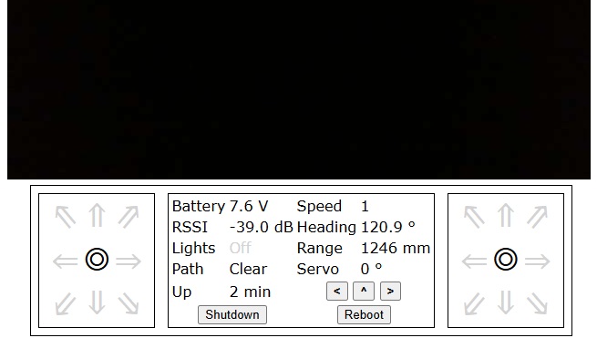
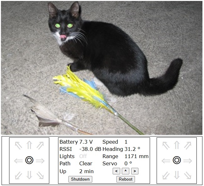
1/06/24 – Finalised and tested the Mecanum movement set, and all associated control code. Working on expanding the web browser UI section that reports status, to nine units of real-time data, plus an additional reboot button. But not tonight.
1/06/24 – Got the entire instrument panel working, as well as lights control, gear changing, and control of the servo position. Tiny bit of tidying up here to do.
4/06/24 – In addition to a complete instrument set, all code for movement based on joystick inputs is complete.
i2c is back to plague me. Push it too fast, and it falls over. Plan is to optimise some sections of code, and see if that doesn’t get me the CPU needed for i2c stability. I’ve done zero optimisation on this project, wanting to see what the STM32F103CB could do. Honestly, I’m surprised it’s coping with almost exclusively floating point math.
5/06/24 – Not knowing where to start with the i2c fault, I’ve gone off isolating potential problem areas, and carefully observing the results. It turns out I have a flawless i2c link when battery voltage is 8.1V, and an almost instantaneously broken one at 7.1V. In probing around at some voltages, I found that the ground level on my PI’s mounting board, is in difference to the one on my Blue Pill +. I expect I’ll have something driveable, as soon as I fix that.
But that will likely be body-off-chassis surgery to rectify that, so tomorrow will have to do.
Later: …and that turned out to be a wild goose chase. Still no i2c resolution.
6/06/24 – Starting to think that the STM32 Arduino Wire library may be the cause. I’ve isolated every subsystem, and twiddled every conceivable contention source, yet i2c remains unstable. If I can’t manage a graceful fault recovery, then we may be looking at a native STM32CubeMX re-wite.
Very limiting, is the discovery that the STM32 Arduino Wire library is deficient. Ordinary Arduino Wire calls, that might have gotten me out of i2c peril, just aren’t implemented in the STM32 version. Can I paste-in some low-level operations, inside the Arduino code?
10/06/24 – Narrowed the i2c problem down to Adafruit’s NeoPixel library, with it’s STM32 code turning off interrupts for the entirety of the time it emits pixel commands (breaking i2c), and screwing with the SysTick timer. Curious that it works at all.
May have to code a suitable replacement. Could cheat, and throw an Arduino Pro Mini at the problem, then go nuts coding extra lighting effects? No, we’ll persevere with the STM32F103CB for now.
16/06/24 – Working on an Arduino compatible WS2812 NeoPixel driver, that doesn’t screw with either the SysTick timer, interrupts or exceptions. DMA fed PWM timers are out of the picture, as Arduino’s use of HAL calls makes this impractical. Yet, I have one trick left up my sleeve, and it involves (ab)using the STM32’s DWT counter. I’ll wanna take my time and get it right, as so many other Arduino users find themselves with similar NeoPixel driver issues.